 "Rusty Vandura - www.tinyurl.com/keepoppo" (rustyvandura)
09/23/2018 at 20:22 ē Filed to: None
 0
0
 28
28
 "Rusty Vandura - www.tinyurl.com/keepoppo" (rustyvandura)
09/23/2018 at 20:22 ē Filed to: None |  0 0
|  28 28 |


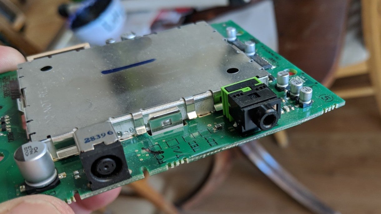
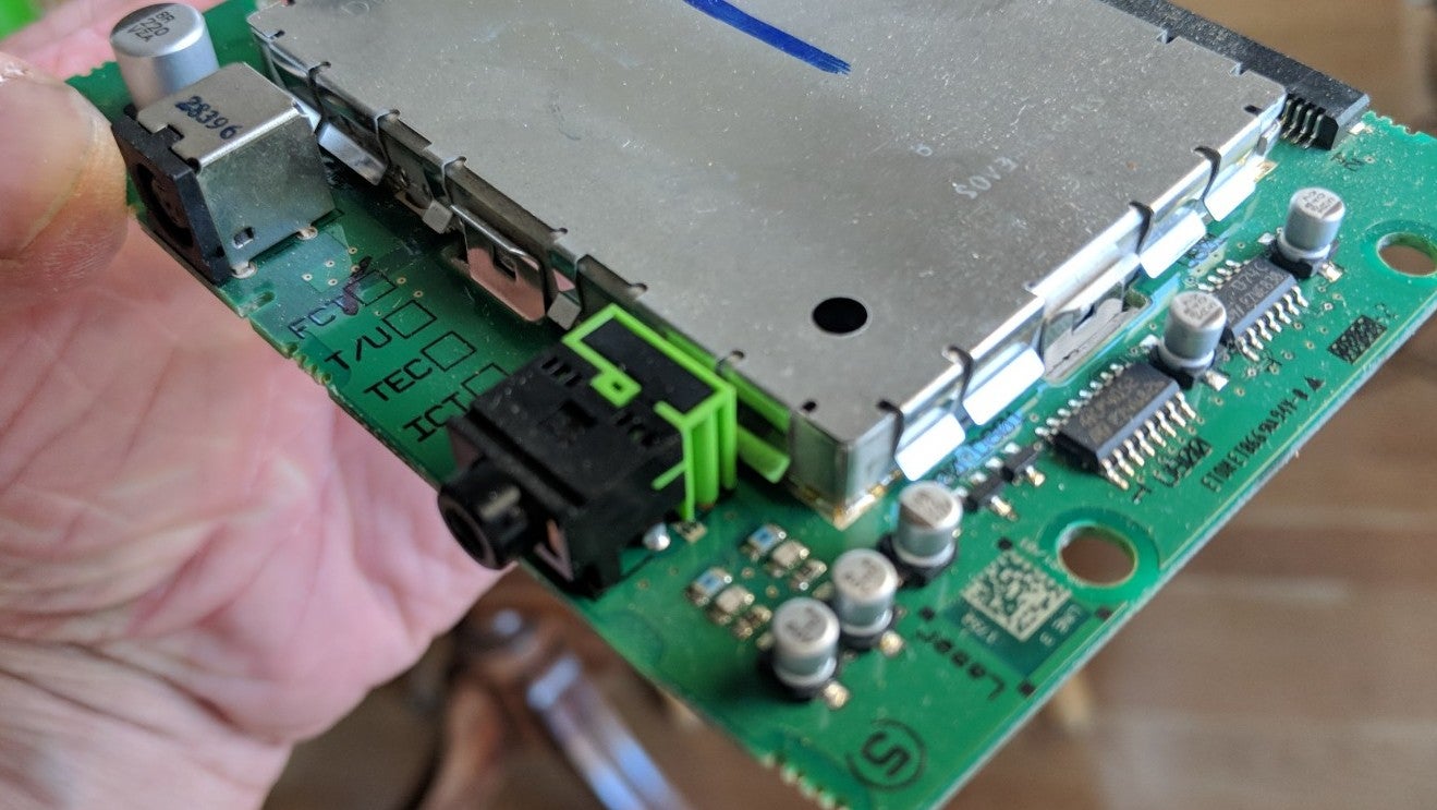
This is the control board out of a Bose Sound Dock II. The aux jack is toast. Iíd like to solder on a dongle with an aux jack on the end. I donít know how. Do any of you do this sort of hacking?
 JawzX2, Boost Addict. 1.6t, 2.7tt, 4.2t
> Rusty Vandura - www.tinyurl.com/keepoppo
09/23/2018 at 20:33 |
|
You sure itís the jack? The soldering looks fine and those things are tough as hell...
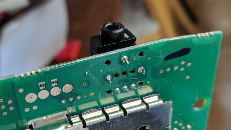
Those three small pins on the back will be the signal connectors. One will be ground and then left and right positive.
I can provide additional tips if needed....
some quick vids:
 Clown Shoe Pilot
> Rusty Vandura - www.tinyurl.com/keepoppo
09/23/2018 at 20:38 |
|
in the bottom pic you posted, the 3 pins in a triangle are likely just there to hold the jack in. T he 3 pins in a line at †the bottom of the jack are likely to be your signal pins. I f you unsolder all 6 of them and remove the b usticated jack, thereís a chance there could be markings on the top of the board (under the connector) that tell you what the pins are.
If there are no markings, you might be able to trace out where the pads run to. One of them may be ground and might just be connected to a nearby ground plane. I canít tell for sure, but the left most pin in the line might be connected to the ground plane. If thatís true, then youíre 1/3 of the way there.
You might want to look for a part number on the busted jack. Digikey might have a replacement part for a couple bucks.
 Rusty Vandura - www.tinyurl.com/keepoppo
> JawzX2, Boost Addict. 1.6t, 2.7tt, 4.2t
09/23/2018 at 20:49 |
|
There are three large and three small pins. Are you talking about the three small pins in a row?
 Rusty Vandura - www.tinyurl.com/keepoppo
> Clown Shoe Pilot
09/23/2018 at 20:50 |
|
I would just install a dongle with a female aux jack on the end of it so would only need to solder wires to the board.
 Clown Shoe Pilot
> Rusty Vandura - www.tinyurl.com/keepoppo
09/23/2018 at 20:58 |
|
Itís still worth giving digikey a shot. The difference between it looking factory and looking like itís done w/ spit and duct tape is probably not more than $5
 SilentButNotReallyDeadly...killed by G/O Media
> Rusty Vandura - www.tinyurl.com/keepoppo
09/23/2018 at 20:59 |
|
The small pins are the signal wires. The large ones are purely mechanical. The left most looks like itís ground while the other two are each left and right channel... youíll have to figure out which.
Soldering iron (low heat!!) , electronic solder and desoldering braid are all you'll need.
 I like cars: Jim Spanfeller is one ugly motherfucker
> Rusty Vandura - www.tinyurl.com/keepoppo
09/23/2018 at 21:05 |
|
Hereís what I would do. Take a stereo aux cable, strip the ends, and hold them on the three points (the side by side ones) and rearrange until the system makes sound while plugged in (just make sure you donít touch any part of the power section while doing this with the power on. It, uh, might hurt). You now know which point is L, R, and G. Now just solder your new dongle on.
 Rusty Vandura - www.tinyurl.com/keepoppo
> Clown Shoe Pilot
09/23/2018 at 21:09 |
|
Fair enough. But functionality is the primary consideration and a robust Frankenstein solution is preferable to me than a less robust solution that looks like someone had a clue. Do you have the skills to do this?
 Rusty Vandura - www.tinyurl.com/keepoppo
> SilentButNotReallyDeadly...killed by G/O Media
09/23/2018 at 21:09 |
|
You wanna do it for me? Iíll mail it to you...
 Rusty Vandura - www.tinyurl.com/keepoppo
> I like cars: Jim Spanfeller is one ugly motherfucker
09/23/2018 at 21:10 |
|
That sounds dangerous enough, and low-tech enough, that I just might pull it off.
 JawzX2, Boost Addict. 1.6t, 2.7tt, 4.2t
> I like cars: Jim Spanfeller is one ugly motherfucker
09/23/2018 at 21:14 |
|
actually not a bad idea.
 I like cars: Jim Spanfeller is one ugly motherfucker
> JawzX2, Boost Addict. 1.6t, 2.7tt, 4.2t
09/23/2018 at 21:22 |
|
Almost like Iím an electrical engineer. Almost.
 Clown Shoe Pilot
> Rusty Vandura - www.tinyurl.com/keepoppo
09/23/2018 at 22:01 |
|
I do indeed have the skillz
 Rusty Vandura - www.tinyurl.com/keepoppo
> Clown Shoe Pilot
09/23/2018 at 22:21 |
|
Would you consider modding it for me if I mailed it to you? You donít live in Europe or Asia, do you?
Drop me a line? oliphant.chuckerbutty@gmail.com
 itranthelasttimeiparkedit
> Rusty Vandura - www.tinyurl.com/keepoppo
09/23/2018 at 22:41 |
|
find a local university and get an electrical engineering student to figure it out, give you a part #, and solder it back on for a case of beer....
 Eric @ opposite-lock.com
> Rusty Vandura - www.tinyurl.com/keepoppo
09/23/2018 at 23:06 |
|
Through hole is easy. Just make sure youíre using the right heat level, depending on the type of solder that was used.
However, it all depends on your skill with soldering.
 Eric @ opposite-lock.com
> Clown Shoe Pilot
09/23/2018 at 23:07 |
|
Iíd just multimeter it to identify the working pins, then deduce from there.
Or just get the same component and swap it out, as you said. It is probably a standard pin pattern.
 Eric @ opposite-lock.com
> SilentButNotReallyDeadly...killed by G/O Media
09/23/2018 at 23:12 |
|
Depending on the type of solder, low heat might not do anything.
 SilentButNotReallyDeadly...killed by G/O Media
> Eric @ opposite-lock.com
09/23/2018 at 23:25 |
|
Most boards like this will have solder that melts under a decent hot air gun. Too much heat tends to damage ICs and even lift tracks...and hot melt solder would take longer to assemble which is a very important cost parameter in the manufacturing of consumer electronics.
 Rusty Vandura - www.tinyurl.com/keepoppo
> itranthelasttimeiparkedit
09/23/2018 at 23:31 |
|
I can buy the entire board on Ebay for $30, but whoís to say the aux jack isnít lame there, too? Iíd rather have a robust, dependable hack than and elegant fail.
 Rusty Vandura - www.tinyurl.com/keepoppo
> Eric @ opposite-lock.com
09/23/2018 at 23:33 |
|
However, it all depends on your skill with soldering.
Zero experience. I have mad skillz in many areas, but this ainít one of Ďem. You got soddering
skillz?
 GLiddy
> Rusty Vandura - www.tinyurl.com/keepoppo
09/24/2018 at 00:00 |
|
How do you know the jack is bad?
This is pretty straightforward. You have 6 pads that need to be desoldered. 3 pads are for the signal (I assume it is a 3.5mm stereo jack) and 3 are for mounting. Youíll need a soldering iron and a solder sucker. Heat the lead and pad simultaneously until the solder becomes liquid and then suck the solder out. It will likely still be adhered to the pc board, but usually you can reheat the lead and move it around to break it loose. When you complete all 6 leads, extract the old jack and replace it.
Be sure you map out which signal lead goes to what conductor on the cable, ďringĒ, ďslee veĒ, and ďtipĒ.† You probably wonít find the exact replacement part so just solder leads to the pc board and attach them to your replacement jack.
 Eric @ opposite-lock.com
> SilentButNotReallyDeadly...killed by G/O Media
09/24/2018 at 10:52 |
|
Doesnít everyone use the high heat RoHS solder these days?
 Eric @ opposite-lock.com
> Rusty Vandura - www.tinyurl.com/keepoppo
09/24/2018 at 10:53 |
|
Yes, but no equipment. I havenít worked anywhere with the equipment in over a year and havenít had reason to do it in a number of years.
 tromoly
> Rusty Vandura - www.tinyurl.com/keepoppo
09/24/2018 at 13:49 |
|
Buy a new aux jack on Amazon and resolder it, did that with my old Asus ROG a few years ago. Some desoldering braid to remove old solder and clean the hole works wonders.
 Rusty Vandura - www.tinyurl.com/keepoppo
> Eric @ opposite-lock.com
09/24/2018 at 15:57 |
|
One Oppo sent me some YouTube video links. I think Iíll give it a shot. I can buy a used replacement board on Ebay readily.
 Rusty Vandura - www.tinyurl.com/keepoppo
> tromoly
09/24/2018 at 15:59 |
|
People modify old school car radios and the like to add aux jacks and even Blue Tooth modules. Thatís what gave me the idea. Iím going to do some YouTube crawling and give it a go.
 SilentButNotReallyDeadly...killed by G/O Media
> Eric @ opposite-lock.com
09/24/2018 at 18:20 |
|
Donít know to be honest though I'd presume so . It also depends what you mean by high heat. The RoHS compliant solder Iím using at the moment melts at the barest touch of a half hot soldering iron...